ebalance-plus hierarchical architecture
The ebalance-plus project aims to provide an energy balancing platform, ensuring flexibility, security, stability, resilience and scalability of the distribution grid. The concept comprises a set of management units that increase the flexibility of the energy platform employing smart grid solutions.
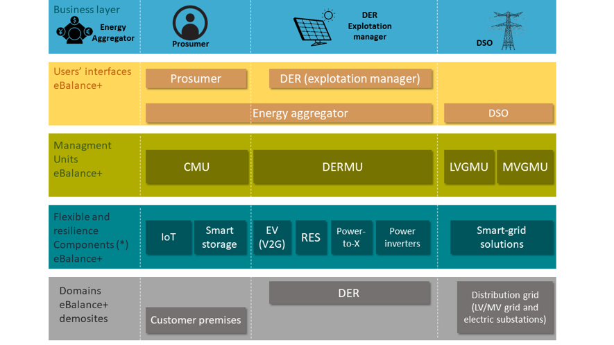
The Smart Grids Architecture Model (SGAM) consist of five levels:
Customer premises, Distributed Energy Resources (DER) and distribution grids comprise the bottom layer.
The second layer is composed of the seven technologies developed within ebalance-plus project with aim to increase the flexibility and the distribution grid observability.
The management units that control the different fields and components are located in the third layer.
The fourth layer is where the user’s interfaces and the different components exchange information to increase the interoperability for prosumers or increase the grid resilience for Distribution System Operators (DSO).
Finally, the business layer is on top, where the main component is the energy aggregator.
To ensure scalability, the ebalance-plus model is based on a hierarchical architecture, where each management unit is coordinating a lower level, as shown below in Figure 2.
The management units are:
- Top Level Grid Management Unit, (TL-GMU). This is the core of the Smart Grid distribution intelligence. It is in charge of the management and control commands in the downstream, and is also responsible for data reception from the systems and devices that lie in lower levels.
- MV Grid Management Unit, (MV-GMU). This unit installed in the Primary Substation (PS), (High Voltage-Medium Voltage, HV/MV), at MV level controls all the Low Voltage GMU (LV-GMU) below this PS, and provides flexibility to the next level, Distribution System Operators – Transmission System Operator, (DSO-TSO). Moreover, this unit provides resilience mechanisms to optimize power flows and to apply “Fault, Detection, Isolation and Restoration” (FDIR) services.
- LVGrid Management Unit, (LV-GMU). This unit installed in the secondary Substation (SS), (Medium Voltage -Low Voltage, MV/LV), at LV level is responsible for providing information about quality parameters from all Costumer Management Units (CMU), Distributed Energy Resources Management Units (DERMU) and smart-grid technologies allocated in the same LV distribution grid.
- Customer Management Unit, (CMU). This unit controls smart-appliances, collects consumption information and energy quality parameters from the smart-meter, and manages the power level of the power inverters supplying local renewable sources.
- DER Management Units, (DERMU). The DERMU is installed along with every DER asset for managing and exploiting the DER by exchanging commands with the ebalance-plus platform.
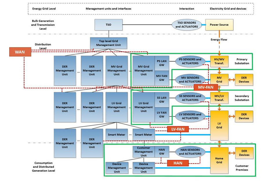
The communication between the different elements runs on four levels:
The top-level corresponds to the Central Management Systems (CMSs), where the TL- GMU resides. The information from the systems and devices in lower layers is received by an upstream communication link, whereas it can send commands to them by a downstream one.
The second level is constituted by the PSs. Each one has an MV-GMU, being responsible for collecting the data from sensors and issuing control commands to MV actuators located within the PS. MV-GMU interacts with DERMUs as well as with LV-GMUs located at the SSs.
The next level is composed by the SSs, which are in charge of the LV energy distribution at the neighborhood scale. In the same manner that PS, each SS comprises an LV-GMU, which receives data from LV sensors, smart meters and DERs located in LV level and delivers management and control commands to LV actuators and DERs.
Finally, the prosumer premises constitute the bottom and fourth level. On this level the smart meter is directly connected to the CMU, the smart meter controls advanced power functionalities and manages the power outputs of energy based on the set points issues by the LV-GMU. At the device level, the Device Management Unit (DMU) interacts locally with smart device sensors and actuators.
Network areas
The location and information exchange between the main components of the ebalance-plus platform gives us a better insight into the network areas that will address the communication needs of the entities involved in the hierarchical architecture.
Communication between the TL-GMU, MV-GMUs and LV-GMUs is performed through a Wide Area Network (WAN) to cover the large geographical deployment that comprises the top levels of the architecture.
In a Primary Substation, we can find a local grid subnet composed of sensor/actuator nodes that along with DERMUs are available to communicate with MV-GMU through the MV Field Area Network (MV-FAN).
The lower level is constituted by Secondary Substations, which are responsible for LV energy distribution. Connectivity between the LV-GMU, smart meters, LV field sensors/actuator and DERMUs is accomplished through the LV Field Area Network (LV-FAN).
A Home Area Network (HAN) is used at the bottom level made up of prosumer premises. The smart meter is directly connected to the CMU and it is connected to appliance sensors, actuators and DMUs.
- increase the flexibility of communication,
- obtain a higher grade of observability of the grid by employing a set of management units,
- reduce energy consumption through a set of energy storage solutions.
Stay tuned for more updates on the ebalance-plus energy balancing platform and check the demonstration cases for more detailed information about the technology implementation.